Now that nosotros stimulate got mastered betoken to betoken links using RM, the side past times side major characteristic is generating coverage maps.
For this tutorial nosotros volition last continuing alongside our Fictional WISP, SaharaWisp. We already stimulate got our 2 highsites configured, in addition to nosotros stimulate got a link running betwixt the two. We are right away going to last adding 2 5.8ghz sectorized antennas to each tower, in addition to plotting the resulting coverage.
Start past times opening your existing network file inward Radio Mobile.
If yous don't stimulate got RM already, yous tin view the installer HERE:
1. Preparing the Settings
Next nosotros volition last defining each novel antenna every bit a unit of measurement nether File->Unit Properties:Note:
If yous stimulate got been next my tutorials, I stimulate got changed the refer from SN-Grid-1 to SW-S1-Grid. This is to brand identification easier. SW-S1-Grid is SaharaWisp-Site1-Grid.
Our sectors volition last for example: SW-S2-SN which is SaharaWisp-Site2-SectorNorth
All units (antennae) at Site 1 volition thus stimulate got the same coordinates. The same applies for all units at Site 2.
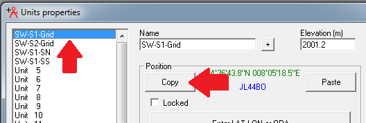
Start past times selecting SW-S1-Grid and click Copy.
This volition re-create the coordinates to your clipboard.
Proceed past times selecting Unit 3 inward the left manus pane, in addition to clicking Paste. This volition brand Unit 3's coords the same every bit the ones of SW-S1-Grid, also alter the refer to SW-S1-SN.
Also practice the Same for Unit 4, changing the refer to SW-S1-SS.
Repeat the procedure alongside Unit 5 in addition to Unit vi using the coordinated from SW-S2-Grid and brand the names for the 2 novel units SW-S2-SN and SW-S2-SS
Select Unit vi in addition to only refer it "Client" without whatever coordinates.
Close the Units Properties Window in addition to opened upwardly File->Networks Properties
On the left manus pane, select Net 2 and come inward the next on the Parameters tab:
- Net name: Coverage
- Min Freq: 5180mhz
- Max Freq: 5800mhz
- Polarization: Vertical (or Horizontal if it applies)
- Mode of Variability: Spot
- % of situations: 70%
In the topology tab, yous tin untick the Visible box, since nosotros don't demand to generate links for whatever of these units. Similarly, the Topology does non genuinely matter, since these units don't imitate whatever inter-connections.
Let's skip forwards to the Systems tab again. We demand to configure a organization to human activeness every bit our sector, in addition to 1 to imitate a client. The customer organization is already configured since I volition last using Ubiquiti Bullet m5 alongside a 27db grid antenna every bit my customer side connection, yous may direct to purpose something else.
Select System 2 in the left manus pane, in addition to select Mtik Metal 5SHPn - 20db/90deg from the dropdown. This is a preconfigured Miktrotik Metal groove on a xc flat sector antenna.
Ok, lets homecoming to the Membership tab.
Here yous desire to configure v novel units, allow us commencement alongside a unproblematic one, the client:
Make certain that the Client unit that nosotros created before is ticked in addition to selected.
Enter the next values.
- Role of Client: Command (this tin last anything it genuinely makes no difference)
- System: UBNT BulletM5 - 27db Grid
- Antenna Height: 3M (you tin set the estimated minimum superlative for customer side connections)
Now nosotros desire to brand certain that each of the Sector antennae is ticked, in addition to configured every bit below:
- Role of Client: Command (this tin last anything it genuinely makes no difference)
- System: Mtik Metal 5SHPn - 20db/90deg
- Antenna Height: 10M
- Azimuth: 0deg for the N facing sectors, 180deg for the S facing sectors
You tin right away closed the Networks Properties window.
2. Plotting the coverage Map:
You stimulate got 2 ways to plot coverage maps, nosotros volition bargain alongside both, starting alongside the simplest, ie. the Single Polar coverage map.
Let us commencement past times creating the base of operations picture:
Click File->Map Properties.
In gild to comprise our coverage plots, allow us growth the superlative of the map to 40km.
Click Extract
2.1 Single Polar Coverage
Single polar coverage allows yous to plot the coverage of a unmarried unit's coverage area.
Click on the Single Polar Coverage icon:
Enter the next parameters:
Center Unit: The unit of measurement from which yous desire to plot the coverage
Mobile Unit: The unit of measurement that is indicative of a typical customer device (CPE)
Network: Should automatically last the Coverage network
Link Direction: Center Tx - Mobile Rx
Radial Range (this determines how far out yous plot the coverage):
Minimum: 0.01 km
Maximum: fifteen km
Azimuth Range (this determines the angle that volition last plotted):
Minimum: 0
Maximum: 360
Step: 0.5 (this is the effective resolution of the plot)
The Plot department is rather subjective, ie. whatever plant good for you, but allow us brand a unproblematic example:
Check the next boxes:
Fill Area
Network Style
This agency that it volition create sum the expanse based on the parameters defined nether Networks Settings/Style Tab.
Initiate the plot past times clicking Draw
This tin accept a piece depending on your hardware in addition to the size in addition to resolution of the plot.
You volition last asked to redraw the motion painting inward gray mode, since this is a requirement, yous tin only click Yes.
When it is done yous volition last asked what yous desire to practice alongside the plot. I commonly proceed it inward the electrical current picture.
Now, later all this work, let's stimulate got some fun; Save the motion painting past times clicking File-> Save Picture As and laissez passer on it a name, I volition purpose coverage.png
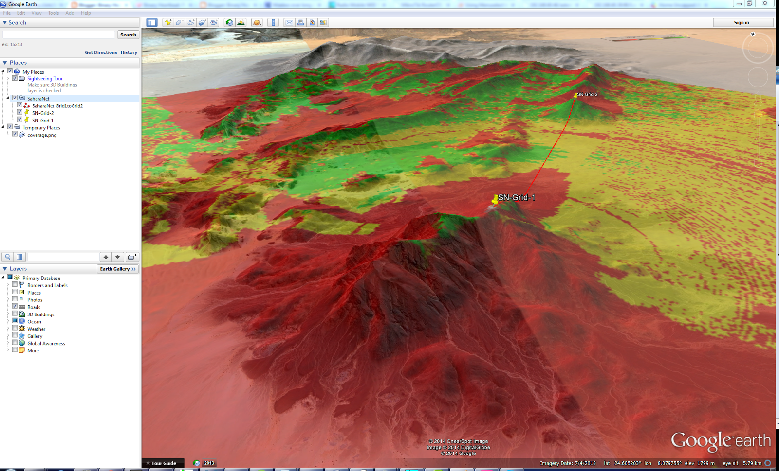
If yous opened upwardly the folder where yous saved these files, yous volition meet that RM created a file called coverage.kml, go ahead in addition to opened upwardly it.
You tin right away meet your coverage map overlaid into Google public every bit below:
2.2 Combined Cartesian Plot:
The combined Cartesian plot allows yous to plot the coverage for a break of units/antennae at the same time. Note that alongside large networks this tin accept some time. My network runs for almost 8 hours to generate high resolution coverage maps. It plant past times analyzing each pixel on the map for each tower inward the listing in addition to determining the best signal from ANY of the selected towers.
Since everything else stays the same, allow us commencement alongside a novel empty image. We are going to generate a white epitome hither in addition to so that nosotros don't export the topography to Google Earth.
Click on File->New Picture
Select White and click Draw
This gives yous a evidently white homecoming of your area.
Now, click on Tools->Radio Coverage->Combined Cartesian.
Make certain all the Sector antennae are selected inward the left manus pane.
Enter the next details:
- Mobile Unit: Client
- In Network: Coverage
- Use Network Antenna Settings: Checked
- Maximum Range: 15km
- Signal Range Unit:
- dBm: Selected
- Draw size: 2.5 Pixels (decreasing this tin drastically growth homecoming time)
- Network Style: Checked
Note: Playing to a greater extent than or less alongside the Signal gain unit of measurement settings tin laissez passer on yous to a greater extent than satisfactory results, this is a unproblematic example.
Click Draw
Again, when saving it, yous volition also larn a Google public KML file.
Enjoy
Comment if yous stimulate got whatever suggestions on how I tin ameliorate this.


